BW_Hummer H3
Well-Known Member
- Messages
- 1,092
- Location
- Texas
I thought I share how I built my switches and custom SPOD set up since I couldn’t really find anything about it already. My reasoning for wanting to do a set up like this was because I already had a front light bar on my roof rack and a winch hooked up to my battery and I was about to add rear facing lights in the rack. The engine bay was really starting to get cluttered with wiring and fuses and looked really messy. Not to mention not the safest to have a bunch of different wiring hooked up to the battery. So looked into different rocker switch set ups. 4x4SPOD makes really nice set ups for For all kinds of jeeps/trucks but as usual nothing for Hummers. Not to mention they were very expensive for even a generic set up. I thought about building my own fused relay box, but that seemed like a lot of time and possible errors. So I looked into off brand spod set ups and found Apollointech switch control system for a JK. Looked into on different forums and found out that it was legit and identical to the 4x4SPOD. Bought for a $160 off of Amazon. Here is a write up on how to use this kit on a H3. My phone broke in the middle of building this so I am missing some pictures so I’ll have to use some stock photos of some stuff.
Here is the link to the kit and apparently they have changed the name of it but it is the same one I bought, but with a different name.
https://www.amazon.com/WATERWICH-6-Switch-Overhead-Control-2007-2018/dp/B07KLG5GJX
It comes with 6 single din back lighting to the switches and a battery gauge reader.
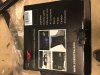

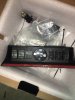
It comes overhead switch mount for a JK and a bunky mount for all the fuses and relays for the engine bay. Which are totally useless to the H3, but I’ll post the pics anyway.
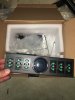
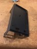
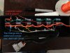
Basically all you need was the wiring harness for the switches that goes from fuses and relays to the switches and of course the fuse and relay panel. I don’t really have a good picture of the wiring harness but here it is
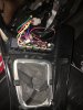
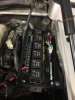
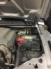
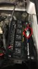
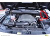
I mounted the fuse/relay panel in this area of the engine behind the battery. Basically the only spot in could fit(sorry for the bad stock photo)
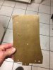
For I got some cardboard and drew of a template of what was going to mount the fuse/relay panel on and cut it out from some scrap metal
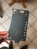
Finished up all the holes needed to mount the panel with how I mounted it in the engine bay
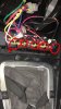
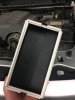
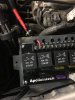
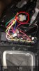
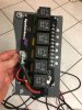
Here it is with the fuse/relay panel mounted on with the wiring harness attached.
Drilled in the mounts with metal screws. Wish I could have found a better way to mount but this was the best way I could see
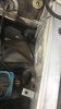
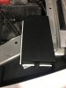
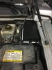
Mounted up without the lid on yet
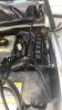
To fit the wiring harness through your going to have to drill a hole in the firewall. I was using the hole for the emergency brake for all my wiring but I need just a little bit bigger hole. So I drilled a 1 1/4inch hole where the clutch would be in a manual H3 in the firewall
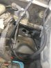
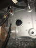
Bought a daystar firewall boot for the whole to keep fit wall shut other than the wire. And fixed the e-brake boot
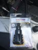
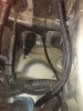
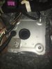
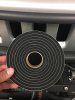
Once you put the wire to from the fuse/relay panel to the switches in the cab put a zip tie around the boot to keep everything out.
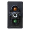
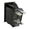
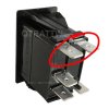
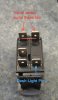
On to the interior. All the interior stuff I got from OTRATTW and highly recommend there products.
Bought a 6 switch mount
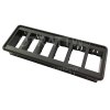
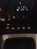
Decided to mount it in front of the shifter where the change holder was
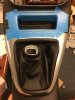
Get to cutting
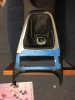
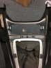
Had to notch out a part under the console, but it doesn’t effect the clips
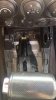
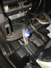
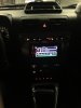
Here is is with the switches in( not sure why my console around the shifter looks dented because it’s not.
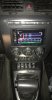
I’ll finish how I wired it all up in the next post along with how it looks all finished.
Sent from my iPhone using Tapatalk
Here is the link to the kit and apparently they have changed the name of it but it is the same one I bought, but with a different name.
https://www.amazon.com/WATERWICH-6-Switch-Overhead-Control-2007-2018/dp/B07KLG5GJX
It comes with 6 single din back lighting to the switches and a battery gauge reader.
It comes overhead switch mount for a JK and a bunky mount for all the fuses and relays for the engine bay. Which are totally useless to the H3, but I’ll post the pics anyway.
Basically all you need was the wiring harness for the switches that goes from fuses and relays to the switches and of course the fuse and relay panel. I don’t really have a good picture of the wiring harness but here it is
I mounted the fuse/relay panel in this area of the engine behind the battery. Basically the only spot in could fit(sorry for the bad stock photo)
For I got some cardboard and drew of a template of what was going to mount the fuse/relay panel on and cut it out from some scrap metal
Finished up all the holes needed to mount the panel with how I mounted it in the engine bay
Here it is with the fuse/relay panel mounted on with the wiring harness attached.
Drilled in the mounts with metal screws. Wish I could have found a better way to mount but this was the best way I could see
Mounted up without the lid on yet
To fit the wiring harness through your going to have to drill a hole in the firewall. I was using the hole for the emergency brake for all my wiring but I need just a little bit bigger hole. So I drilled a 1 1/4inch hole where the clutch would be in a manual H3 in the firewall
Bought a daystar firewall boot for the whole to keep fit wall shut other than the wire. And fixed the e-brake boot
Once you put the wire to from the fuse/relay panel to the switches in the cab put a zip tie around the boot to keep everything out.
On to the interior. All the interior stuff I got from OTRATTW and highly recommend there products.
Bought a 6 switch mount
Decided to mount it in front of the shifter where the change holder was
Get to cutting
Had to notch out a part under the console, but it doesn’t effect the clips
Here is is with the switches in( not sure why my console around the shifter looks dented because it’s not.
I’ll finish how I wired it all up in the next post along with how it looks all finished.
Sent from my iPhone using Tapatalk
Last edited: