• Welcome to H4O! For a reduced ad experience, please login or register with the forum.

SO.... is there really no way to fix the steering rack issue on the H3?

alrock

El Diablo
Staff member
Messages
10,677
Location
Scottsdale
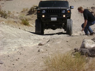
Can't find the pic. It is from April 2010 with Hunner going up a rock on Steel Bender in Moab. Wheels were pigeon toed as his BP tie rods flexed. Wasn't a camera trick - as I spotted him I could not actually tell which way his tires were pointing so I couldn't tell him which way to turn. Had the same issue on Green 1's H2 (when he had one) which I think had Fabtech tie rods.
 

jakesz28

Well-Known Member
Messages
1,056
Location
Cabool MO
I saw the pic you were talking about. It looked broken. Dont remember what thread it was in, either.

I think I will be making me some steel bushings for my rack mount and adding the second mount. With access to a lathe I can my the steel sleeves any size I need to fill the clamp.
 

cbetts

NERD!!!
Messages
3,188
Location
Rancho Palos Verdes, CA
I have seen the pigeon toe on all the H2s running the FabTech but I think that is an effect caused by the front lifting up, dropping the front wheels to the point where the distance from the steering knuckles to the rack is increased, thus pulling the knuckles inward and causing the tires to pigeon toe.

Here are some pics of JRWid's rig on Last Chance Canyon.

(click to view larger image)


06 H3

a.k.a. "The Jackal"
Messages
9,506
Location
Meridian, ID
FOUND IT! :hans:


8xs0201.jpg
 

alrock

El Diablo
Staff member
Messages
10,677
Location
Scottsdale
That's way more flex of the tie rods than ive ever seen on a stock H3, including my pic from April on Hells Gate where I was maybe 1/4 of that toe in.

Sent from my VS910 4G using Tapatalk 2
 

atvspeed4

Well-Known Member
Messages
1,216
Location
massachusetts
That's way more flex of the tie rods than ive ever seen on a stock H3, including my pic from April on Hells Gate where I was maybe 1/4 of that toe in.

Sent from my VS910 4G using Tapatalk 2

If you go to the tie rod thread and see the discussion I explained that it was not from flex but the change of geometry when clevis are used to adapt heims to the steering rack and also raising the pivot point from attach point on the knuckle. The clevis in effect widens the rack and changes the geometry hence when at full droop the wheel points in towards the center.
 

alrock

El Diablo
Staff member
Messages
10,677
Location
Scottsdale
Other non- toed-in H3s with virtually no front end weight on them. The geometry should be the same on BP vs. OEM, meaning same starting and ending points for the tie rods, so the difference is how the BPs handle themselves.
1250413122_2b8oq-L-1.jpg


1250409156_ziKDY-L.jpg


This is the most toe-in I've seen on a stock H3 and this has the benefit of side force
Moab-April-2012-060-L.jpg
 

atvspeed4

Well-Known Member
Messages
1,216
Location
massachusetts
The starting point and end point are not the same with the bulletproof tierods but it is the best thing we have yet. I have definitely seen my stock tierods flex and even have a slight bow in them. We need to figure out a solution to the steering in our rigs!
 

backcountryislife

Well-Known Member
Messages
858
Location
Dumont, CO
considering that I've broken 3 racks & not a single tie rod yet... I wonder, is the tie rod that big an issue? Who here has broken a 16MM tie rod?

Or is it the way they work, helping to break the rack that you guys mean?

I wonder, if I had a setup with tie rods with a bend in them, where the force was straight into the rack like what the BP ones do, would this be as big a problem? if flex is an issue... have a set built that are bridged so they're stiff.

Personally, I'd rather snap a tie rod, replace it in the field, then go get an alignment, than keep snapping racks.

I'll drop down a bit for now... but I really don't want to do that either!
 

atvspeed4

Well-Known Member
Messages
1,216
Location
massachusetts
Anyone have a clear front view shot of the h3 suspension so I can draw a few things that may help us discuss this better? It would need to have the outer tie rods visible.
 

atvspeed4

Well-Known Member
Messages
1,216
Location
massachusetts
2 cranked.jpg2 cranked clevis.jpg2 cranked raise outer tierod.jpg2 cranked raise outer tierod with bend.jpg

Sorry for the terrible drawings but here we go. The first pic is of tierod angles at 24" as you can see we are pushing up and in on the rack instead of the in direction it was designed for. In the second picture we raise the outer tierod up on the knuckle to decrease the angle of the tierods and "save" the steering rack. When you do this your tierods no longer follow the same path as your control arm and you will get bumpsteer or strange handling characteristics. The next is our attempt at strong tierods. We go and install clevises, HD tierod sleeves and a magical outer tierod that is strong yet sits tight to the steering knuckle. We have now widened the steering rack and shortened our tierod length how ever slightly. This causes the tierods to follow a different path than the control arms and again we have strange toe in. The last picture uses a clevis and also a heim outer with misalignment spacers. We bend the tie rod sleeve because the heim does not allow us enough angle to match the suspension travel of the h3 at full droop. in doing this we have the same effective length from inner clevis to outer knuckle as the previous example and therefore have the same toe in at full droop but now we also may experience the tierod sleeve slightly rotating at full droop due to the bend.
 

Hunner

Well-Known Member
Messages
2,334
Location
Arkansas
Ok here is my take on all that,
The bend was so the Heim or spherical rod end would sit at rest in the middle of it's articulation limits. That was because of the already high angle of the rods and at the time I was working on fitment to the H3 I had it at 24". I later came down to 23 1/2 so now the Heims are not exactly level at rest.
I do have some fitted misalignment spacers under the outer connection. We tried several. The plan was by having the BP articulate 30 degrees as opposed to 23 on the OEM they would actually reduce stress on the rack, not putting more force because they were bigger therefore throwing out the "fuse theory" When the OEM's max out on rotation then they become a lever on everything.
I DO NOT have bump steer.
I also noticed that my front end did not bounce as much over rough terrain, because the BP tie rods do not have the flex the stock ones do. Randy at BP said that was interesting that I noticed that and wondered if I would.
That shot of mine was a combination of me being high centered on that ledge which takes weight off the front end and creates some tow in, which can be seen if you just jack one up, and pressure on the tire on the ground causing the Heims to articulate to the full extent.
That action is also why to be able to set toe you need the weight on the H3 to be on rotating plates rather than jacking up repeatedly to try to guess at it.
Scary looking, but even though the tie rods might flex some it is very minimal. Mine are not the really big ones because I thought these were going to be the best fit for clearance. There were not 16mm tie rods at the time I had these made and 14mm were out of stock. I figured what the heck, a fun project and I enjoyed the knowledge Randy had thru our online designing process.
If the rack just goes in and out without the upward pressure on the pass side I think they will hold up a lot better. Of course that would be ideal but even with the sleeve the force is on that end, it's just not transmitted to the other secure end. So I figure and did state at some point maybe I might have a seal start leaking at that end but it did not happen on either H3.
I don't know all the solutions but all of this so far has worked.
Since I did not blow up anything in that situation in the picture, I'm sticking with this setup.
I agree bending a stock one would not help but rather max out the ball joint outer end.
In the case of a Rancho lift using their raised knuckles is supposed to keep the tie rods near stock angles while just turning up the torsions an excessive amount increases the angle.
I have thought about using their knuckles alone without the lift, but at one time they would not sell me those separate?
I'm not sure of the result of that.
Something with less height could work but have some made would be involved.
Maybe some of you can think on that?
I have reached my limits on some of this and how it all works on the vehicle as opposed to paper and theory. However I do eagerly follow you guys that have more knowledge and ideas.
Mod on!!
Hope all that made sense.zzzzzzzzzz
 
Last edited:

cgalpha08

"Like Nothing Else"
Messages
3,720
Location
Indianapolis, IN
This may be a completely dumb idea, but what about relocating the outer tie rod mounting location higher up, closer to the middle point of the wheel?

Sent from my DROID BIONIC using Tapatalk 2
 

backcountryislife

Well-Known Member
Messages
858
Location
Dumont, CO
This may be a completely dumb idea, but what about relocating the outer tie rod mounting location higher up, closer to the middle point of the wheel?

Sent from my DROID BIONIC using Tapatalk 2


I think that's what Hunner was talking about in regards to buying the rancho knuckles, which was a though I had as well... but I'm up 1.5" or so, and they're up 4"... so I think that would create issues of it's own, as the tie rods wouldn't be in alignment with the control arms at all anymore.
 

atvspeed4

Well-Known Member
Messages
1,216
Location
massachusetts
I think that's what Hunner was talking about in regards to buying the rancho knuckles, which was a though I had as well... but I'm up 1.5" or so, and they're up 4"... so I think that would create issues of it's own, as the tie rods wouldn't be in alignment with the control arms at all anymore.
Exactly on top of that the upper ball joint attachment point would be 4" higher and that would mean moving the upper control arm up 4" or the lower control arm down 4"...
 

backcountryislife

Well-Known Member
Messages
858
Location
Dumont, CO
Exactly on top of that the upper ball joint attachment point would be 4" higher and that would mean moving the upper control arm up 4" or the lower control arm down 4"...

So you're sayin.... that might not work huh?:)

I do wish there was an easy way to move the tie rod up a bit without negative consequences.

Guess I'm going to buy another stock one from Canada, then mount the piss out of it. I'll have 3 stock mounts, 2 brand new & one with about 2 months on it, if I can fit all 3 that's what I plan on doing.

New rack, new T-case, now I just need to figure out what to do about the F diff.
 

Hunner

Well-Known Member
Messages
2,334
Location
Arkansas
Exactly on top of that the upper ball joint attachment point would be 4" higher and that would mean moving the upper control arm up 4" or the lower control arm down 4"...

yea but,,, lol I also was posing the question of getting some half of that or less. Like I said I have reached the end of my knowledge of all of that and how it starts affecting other things, but I know people that do. I have just not pursued it any further since what I got works for me.

I found one more 2 inch long sleeve bushing I guess I set back until I got the others.
I have a long list of orders but since you are so active on this I would sell it to you if you will give us your feed back. I would like to see your results under extreme conditions.
You mentioned something to the affect your guy did not install the center bracket, do you not do your own work?
I ask because I want to get the full response on how it was installed.
Grinding some on the bracket is my preferred method to solidly mount the sleeve.
PM me
 

06 H3

a.k.a. "The Jackal"
Messages
9,506
Location
Meridian, ID
I just did a quick run through with the truck before my run tomorrow. My steering rack has some play...Im kinda sketched out as you just had a failure so lets just pray I make it home without having to take an arm workout. I also lost one of the grease nipples to the greaseable driveshaft. Idk how the hell that happened.

I hate that feeling when you think tomorrow is gonna end bad. Well I have that feeling but it isnt going to stop me from going...If I dont post up by 8PM tomorrow night I am stuck on the 30 mile Miller Jeep trail. lol
 

Hunner

Well-Known Member
Messages
2,334
Location
Arkansas
You guys are having that sinking feeling I had when my rack broke in 06. That is why I jumped on the tie rods and two rack braces and even the flexible hydraulic line, just in case it broke anyway. At least that way I would not fry the pump. I did not want to continually expect a failure, especially a long way from the house.
Sounds like you both need to carry an extra rack!
Your making me think I need to add the center clamp to the Alpha!! I hated drilling that hole for that thru all those layers of the frame. If you do find my write up on that and allow for the offset where the frame halves come together and are welded to keep the rack in alignment.

Why not do all of the above and then if you crack one we are going to have to put governors on your H3's, and start a driving school, lol Pick your Hummer line and not necessarily what others take, taking into consideration your limits.
You guys are good "test" drivers for how all this works so I look forward to your thoughts on how to fix it.
I put out the info way back in 06 after trying to run 4 inch torsion crank after learning the result, that I thought down to 23 1/2 or less was better for the rack.
I carry enough extra weight in the back that mine is near level with that setting.
I had some warranty work done at one point on the 06 in the front end and when I jumped in to drive it off I thought I had two front flats. They had turned it down to 22 1/2 to do the alignment at stock settings. I was looking at the ground in front of me and thinking something was still broke.
I finally gave in to running 35's when I got some with the Beadlocks as a package and so I will stay at 23 1/2 and work around that for all my other adjustments.
Be sure and check the tightness on the drivers side as well if it has been moving on the pass side.
Also check that bolt that connects the steering shaft to the rack.
 
Last edited:
Top