• Welcome to H4O! For a reduced ad experience, please login or register with the forum.

changing out stock radio finally!!!!!

cbetts

NERD!!!
Messages
3,188
Location
Rancho Palos Verdes, CA
Not really much to it. just use the lighter sockets as a place to grip the dash and gently pull out. Disconnect the wire harnesses connected to the panel and the rest should be self evident. Here are the pics from mine: :link:
 

poncho1965

Well-Known Member
Messages
1,263
Location
Ridgecrest, California
Does this replace a monsoon system? Curious to know how much power you need to at least equal the monsoon...the monsoon display really sucks, like the system though.
 

OIF Marinex3

Well-Known Member
Messages
60
Location
Fredericksburg, VA
Does this replace a monsoon system? Curious to know how much power you need to at least equal the monsoon...the monsoon display really sucks, like the system though.


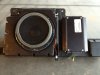
If you have the Monsoon system in your Hummer replacing the head-unit will not affect the monsoon system. all the monsoon system really is Six premium speakers and one 8" Sub all powered by an 8 Ch 200w Amp
$T2eC16R,!)cE9s4PtHz-BQhIY,,QFg~~60_57.JPG$(KGrHqZHJCgFBsO4dC3MBQhIYVbTpg~~60_57.JPG

One effect of having a high quality head unit would be that it could provide too much power to the stock monsoon speakers and blow them, I say this because I installed a Pioneer AVIC-Z140BT (http://www.pioneerelectronics.com/PUSA/Car/GPS-Navigation/AVIC-Z140BH Awsome) and I can/have pushed my speakers to death.

do your settings right on a new Deck and it will really bring the Monsoon system to life, I will be getting some better speakers all around proably just the age of the speakers (6yrs old), but I am keeping the Monsoon Amp.

changing the Head unit in a H3 has to be one of the easiest installs I have ever done, after you the metal tab on the support bar.
 

Lucky's

Member
Messages
7
Location
Southwest Michigan
Hello all, this is my first post on this forum. I am a jeep conversion and have owned my H3 for just a few weeks now. Based on this thread I just ordered this Boss unit and can't wait to get it and get it installed! Thanks for the heads up on it!!!


Shaun
Sent from my iPhone
 

JonBishop

Well-Known Member
Messages
724
Location
Glendora, CA
havent gotten a chance to install just yet but im wondering, anyone know if this head unit needs a mounting kit?...... looking around and cant find one for it, but im thinking it might not need one, if anyone has and knowledge please share :)
 

TXH3T

Well-Known Member
Messages
269
Location
Prescott AZ
I love the head unit and back up camera! I was about to buy it and then remembered the harness required. Isnt it like 500 bucks?
 

skeptic

Well-Known Member
Messages
737
Location
Orygun
Wow, I'm stunned that you can get a head unit like that for $150 and that backup camera for $20. I realize they are deep discounts from MSRP, but still, I had no clue.
 

Lucky's

Member
Messages
7
Location
Southwest Michigan
havent gotten a chance to install just yet but im wondering, anyone know if this head unit needs a mounting kit?...... looking around and cant find one for it, but im thinking it might not need one, if anyone has and knowledge please share :)

I got mine in and you definitely need a mounting kit. I've just got it in there for now an have a mounting kit on order. So far I'm very happy with the performance and functionality.


Shaun
Sent from my iPhone
 

f5moab

Mr. Beretta
Messages
2,000
Location
In hiding.....
Old thread I posted on another forum many moons ago for my radio install in my 06. It involves the Pionner Z1 (so that dates it) and I have made some changes here to reflect things I found out over the years and the transfer of the radio to the 08 H3.

Prior to starting installation, I soldered all the wires between the Peripheral adapter and the radio. (NOTE: I found the Peripheral adapter to be inferior to the GMOS-04 adapter I installed in my 08 for the Z1 and in this past few months for the install of the Pionner XT940. Also, the GMOS does not require you to connect into the back up wire for the camera to turn on, or the VSS input. It detects these inputs via the serial data link. This might be true of other adapter, but cannot say that from experience. I have left in the procedures for connecting to a backup signal wire and to the VSS for those "just in case" scenarios. The text has been grayed, but can always be copied to word or another program for printing...if ever needed.)
Grounds (EXCEPT FOR THE CAMERA),
Hot leads (B+ - yellow, and Acc – Red), etc.,
Speaker wires,
Amp signal wire,
Mute wire,
Illumination wire with Z1 adapter in place,
Chime Adapter from Peripheral.

The camera ground and hot are connected to the box, so it is best to just butt connect the ground wire for the camera splitter box after it is installed and the wire is run under the dash. The power wires for the camera have an inline fuse that you can separate, so you can solder this wire into the ACC wires, and still run the hot wire under the dash.

Radio Removal:
1. Apply the park brake, and place the transmission lever in 1st gear. (This allows room for the center trim panel to be removed, and for a place to sit the NAV unit during install.)
2. Using a small plastic tool (a heavy plastic spoon or knife will do), insert it at the top of the center trim panel, where it is fitted to the I/P cover (just above the A/C vents).
3. Pull back on the plastic tool, to allow your hands to get behind the panel, and then pull it back. It is held in place by six fasteners; no screws.
4. Don’t pull too far back, you have to disconnect the following connectors:
Hazard flasher switch connector,
4/4 indicator switches’ connector,
HVAC switch connectors at the bottom,
Accessory plugs connectors,
Any off-road or roof mounted lights that might be installed.
NOTE: There are HVAC connectors, one gray, and one black that are interchangeable between connections. However, the back of the trim panel identifies where the black and gray connectors are inserted into the trim panel.
5. Remove the four screws retaining the radio, remove the radio outward, disconnect the 24-pin and the 12-pin connectors, AM/FM antenna wire, and completely remove the radio.

Rear camera install:
The wiring harness from the camera contains four wires, two grounds (one for power and one for the camera signal), one ignition hot wire, and the camera signal wire. They all end in a 4-pin, non-waterproof connector; therefore, in my opinion, it has to end inside the passenger compartment, away from the elements, where it plugs into a small splitter box. The splitter box splits out the wires from the camera into a hot/ground wires and one wire with RCA connectors on both ends.
My original idea was to run the wire under the vehicle, on top of the left frame rail. I tried this, but the wire was not long enough to reach into the vehicle from the engine compartment.

Camera Mounting and wire routing:
1. Cleaned off the top of the trailer hitch, and allowed it to dry.
2. Mounted the camera to the bracket.
3. Pulled the cover off the two-sided tape on the bracket and pressed it into place.

34782%3A7%3C7%7Ffp347%3Enu%3D3262%3E738%3E7%3B%3B%3EWSNRCG%3D3233%3A438%3B6679nu0mrj


4. I then secured the camera and bracket to the trailer hitch with a large tie strap.
5. I installed about six feet of automotive black conduit to the camera wire harness for protection.
6. Routed the harness and conduit to the left of the camera, through the slot next to the trailer hitch connector.


34782%3A7%3C7%7Ffp348%3Enu%3D3262%3E738%3E7%3B%3B%3EWSNRCG%3D3233%3A438%3B568%3Cnu0mrj


7. Pulled the conduit and harness up, and tie strapped it to the trailer hitch harness.
8. Routed the wire over to the left rear corner. (Keep as far away from the muffler as possible.
9. I tie strapped the camera harness to the small factory harness in the left rear corner, under the car.
10. Lower the left rear seat back.
11. Slide the driver’s seat fully forward.
12. Remove the kick panel molding.
13. Remove the front sill molding.
14. Remove the center sill molding (note: the front sill molding must be removed in order to remove the rear sill molding). Both moldings are just a pull and remove type.
15. At the rear of the vehicle, I pulled the left rear lower compartment trim panel away from the vehicle; I did NOT remove it totally. All I wanted was access to the left rear part of the vehicle.
16. With the panel back, you will notice a square corner with a large square hole. Inside this chamber is an oval hole toward the front of the vehicle. Drop your fish wire down this hole, and the wire will come out under the vehicle.
17. Attach the camera wire that was left under the left rear corner of the vehicle to this fish wire and pull up through the holes out into the rear compartment area.
18. I then fished the wire toward the front of the vehicle, behind the lower trim panel and then under the carpeting. (At this point, I realized the camera wire would not make it to under the I/P.)
19. I installed the camera splitter box under the very rear of the left driver’s seat track. With a power seat, there is no interference with the seat operation; can’t say so for a manual seat, so check first.
20. I then did a small slit in the carpet right next to where the splitter box is mounted.
21. I then fished the camera wire under the carpeting and plugged it into the splitter box.
22. I then fished the three wires (power/ground/camera signal) through the slit in the carpet toward the outside of the vehicle.
23. I ran the three wires under the edge of the carpeting, up the kick panel, over the steering column, and into the radio area.
24. I installed the rear compartment trim panel; make sure to pull the outer weather seal over the trim panel (for reference look at the right weather-strip to trim panel that was not touched.
25. Installed the rear sill molding. Make sure to route the shoulder harness on the outside of the trim panel when installing.
Do not install the kick panel or driver’s door sill molding at this time.


f5moab

Mr. Beretta
Messages
2,000
Location
In hiding.....
FOLLOWING NOT REQUIRED IF USING A GMOS-04 ADAPTER
Reverse Backup Signal Wire (VIOLET/WHITE): (used to turn on the camera automatically in reverse):
1. Remove the screw cover from the A-pillar trim molding (it just snaps out).
2. Remove the Phillips screw.
3. Pull the molding toward the inside of the vehicle, and upward to remove from vehicle.
NOTE: If you have side air curtains, there is no problem removing the A-pillar molding. The inflater module and all the electrical contacts for the side air curtain are in the back, by the C-pillar. Only thing in the A-pillar for the side air curtain is the tie down strap, attached to the frame. Do I need to say, “Do not mess with this strap?”
4. Look for a brown wire in the harness. If you have two brown wires, then you have to check which brown wire is the reverse signal wire from the trans selector. I used a voltmeter and a pin, and tapped both wires. With the ignition On, move the trans lever into Reverse. The correct wire will show battery voltage in reverse, zero voltage in any other gear.
5. Using the little connector that is attached to the Violet/white wire, splice this wire into the brown reverse signal input wire. Note, the violet/white wire has a resistor in line for the new head unit.
6. Route the wire down, inside the kick panel, over the steering column to the radio area.
If you are installing the microphone wire under the A-pillar molding, now is the time to do so.

FOLLOWING NOT REQUIRED IF USING A GMOS-04 ADAPTER
Vehicle Speed Sensor Wire (Pink):
On some early model H3s, the dark green/white speed signal wire is in the 12-pin connector at the radio. It is located in terminal E of that connector. However, be careful, terminal H of the same connector also has a dark green/white wire that is the signal in from the XM radio receiver. If you look at the connector end, termin
al E is noted in the illustration.

34782%3A7%3C7%7Ffp355%3Enu%3D3262%3E738%3E7%3B%3B%3EWSNRCG%3D3233%3A438%3B6678nu0mrj


If the speed signal wire is not in the connector:
1. Remove the right kick panel.
2. You will see a large connector in the kick panel area.
3. Look at terminal A8, there should be a dark green/white wire on one side of the connector and nothing on the other side. This is your speed signal wire.
Tap into the speed signal wire:
4. When you locate the speed signal wire, tap into it using the splice in the NAV package.

XM Receiver Install:

1. Install the XM receiver with the connectors’ locations up.
2. Look into the radio location area under the dash and then look to the right. You will see the XM module mounted horizontally. The Greenish square connector toward the rear is the XM antenna you will use for the Pioneer XM receiver. Push on the bottom of this square connector, and pull the connector from the XM box.
3. I then did some modification to the GM XM antenna connector to allow it to attach to the Pioneer XM receiver. I put a slit into one side and snapped it into place. You probably could completely remove the connector (slide out the white terminal device on the green connector) and remove the wire, then insert it into the wire connector that came with the Pioneer XM antenna. I found it not necessary.
4. Attach the XM antenna to the Pioneer XM receiver.
NOTE: If you are installing Sirius, I would guess the installation is the same, and the GM antenna might be able to be used. But I do not know if the receivers are the same size, or the antenna is the same.Navigation Unit GPS Antenna:
There are two HVAC ducts above where the radio installs. I mounted the GPS antenna to the top side of the right duct.
1. Peeled the plastic off the piece of metal that came with the antenna, and slightly pushing up on the bottom side of the I/P cover, I moved it as far forward as possible, and then pressed it into place on the top of the duct.
2. Positioned the GPS antenna to the metal plate. The antenna is held in place with the magnet on the bottom of the antenna.
NOTE: This will work for the GPS antenna, but will NOT work for XM.

FOLLOWING SHOULD NOT BE REQUIRED
Jumper 3 Serial Data wires:
This is dependent upon the revision level of the Peripheral adapter (if you are using another type of adapter, I cannot help). Older Peripheral adapters required you to splice together, with a jumper wire, the three purple Class 2 serial data wires that were in the two GM wiring harness connectors. Reason was the factory radio received the class 2 circuit and then passed it along to the XM receiver and the OnStar module. The Pioneer head unit does not do this pass-through. Therefore, if you have an older Peripheral adapter you must jumper the two purple wires from pins A1 and A1 of the 24-Pin (GM) connector to the purple wire from Pin G of the 12-pin connector. This allows the Class 2 signals to bypass the head unit and allow the factory XM receiver and the OnStar module the ability to continue communications in the bus circuit.
The latest revision of the Peripheral adapters does not require this jumper wire to be installed. The way to tell is look at the Peripheral 24-pin connector that mates to the GM 24-pin connector and see if there are two purple wires coming out of the connector and being spliced together, with a third purple wire going to the 12-Pin connector. If so, you do not have to jumper the wires on the GM connector.
The adapter I received from CarDomain.com was the latest revision, but the instructions to jumper the GM side of the connectors was included. I contacted Peripheral and they agreed, the jumper wire was not necessary.


Radio Face Plate Installation:
The radio faceplate from Schosche requires trimming of the top inside plastic. I trimmed off approximately 1/8 of an inch. Otherwise, when the NAV unit’s front cover opens/closes it will hang up against this plastic piece. (I used a file, but sandpaper or a Dremel would do the same job.)
I also snapped of the little plastic projections on the bottom of the face plate, to prevent any clearance issues upon installation of the center trim panel.
 

f5moab

Mr. Beretta
Messages
2,000
Location
In hiding.....
Pioneer AVIC-Z1 Head Unit Install:

Now the fun really starts…the Nav heat unit installation. This is the time to take a break, have a cold drink, relax, because you are about to shove a big NAV unit into a hole that is packed with more wiring than required by ten factory radios.

1. Position the radio onto the console, in front of the gear shifter; CAUTION, do not scratch the screen, use a towel.
Connect the Peripheral adapter to the 24-pin and 12-pin GM connectors.
2. Connect the pink vehicle speed sensor wire to the pioneer harness.
3. Connect the violet/white reverse signal wire to the Pioneer harness.
4. Butt end the camera ground wire to the grounds you soldered prior to installation.
5. Connect the ground wire to the crosscar beam brace behind the radio area. Just look in and you will see a couple 10mm bolts attaching a brace to the cross car beam. Loosen and slide the ground wire under the bolt, and then tighten.
6. Install the antenna adapter to the vehicle’s AM/FM antenna.
7. Install the microphone lead.
8. Install the NAV GPS lead.
9. Install the XM receiver power/ground connector and the XM signal wire to the XM receiver.
10. Install the signal lead from the XM receiver to the back of the Pioneer NAV unit.
11. Connect the camera’s hot lead to the fuse holder of the wire soldered to the adapter harness.
12. Connect the camera’s signal wire to the signal wire lead from the NAV unit.
13. I attached the chime module to the bracket just above the glove box with two-sided tape.
14. I positioned the super long, thick, XM receiver wire inside the left of the radio opening, just to get it out of the way.
15. I positioned the remaining wires and adapter below where the radio mounts, then slowly slid the NAV unit into the hole, and attached with four screws. If the bracket on the NAV unit does not fit, flush with the I/P, reach behind and move the wire harnesses around until it fits flush. Do not want to cut any wires.
16. Before reassembling the center trim panel, test the unit. Make sure all the attached components such as XM and rear camera operate. Until you call XM to turn on the box, you will get a preview on channel 1 and 0. Channel 0 also gives you the box ID number that you will need for XM.
Test the rear camera, but make sure you follow the instruction manual on setup. You have to turn the feature on via the NAV unit settings screen.
17. Once you feel that everything operates ok, install the center trim panel.
18. Connect all the connectors, and position the panel to the I/P and tap with your hand where the six fasteners are and it will pop into place. Make sure to align the two A/C ducts with the vents in the trim panel.
19. Install the kick panel and sill panel moldings.

Rear Camera View:
34782%3A7%3C7%7Ffp354%3Enu%3D3262%3E738%3E7%3B%3B%3EWSNRCG%3D3233%3A438%3B568%3Anu0mrj


Installed:
34782%3A7%3C7%7Ffp348%3Enu%3D3262%3E738%3E7%3B%3B%3EWSNRCG%3D3233%3A438%3B5693nu0mrj


These procedures are from the install on my 2006 H3, please understand that GM (as well as any manufacture) will sometimes change wire colors in the same model year, and in future model years. So, if you have any doubt, check for voltage at the wire before connecting a wire from the radio.
You can be pretty sure the wires between the factory radio, adapter and new NAV unit will be the same, since these follow a wiring code for radio power, ground, speaker, etc., wires.


The total time for the install was about 4 hours. I did waste about a half-hour on the wiring for the camera along the top of the frame rail, just to remove it and start over again. So, this install should take someone familiar with automotive wiring and trim panel removal about 3-4 hours.
 

Lucky's

Member
Messages
7
Location
Southwest Michigan
All and all for the money I'm very happy with it. I'm sure some of the more expensive units have a little more responsive screens or more options, but for the money it works great. The Bluetooth integration is flawless and that's one of the biggest reasons I wanted it. DVD player works great, too. I got the mount kit from the post above and it fit great. Thanks for that link!

ImageUploadedByTapatalk1356224467.052664.jpg
ImageUploadedByTapatalk1356224480.948602.jpg
ImageUploadedByTapatalk1356224493.931983.jpg


Shaun
Sent from my iPhone
 

Attachments

  • ImageUploadedByTapatalk1356224421.315320.jpg
    ImageUploadedByTapatalk1356224421.315320.jpg
    184.8 KB · Views: 821

JonBishop

Well-Known Member
Messages
724
Location
Glendora, CA
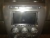
finally got it installed!!! hahaha took me long enough

a dark shot of it
0A4392C7-FD32-4865-A8D5-7D3EEAB0A846-2348-00000191E0F34E2C.jpg


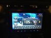
with the dome light on, i used some plasti dip on the ring around the shifter and the piece around the nobs an radio, gotta say im lovin the way it looks
93504D7A-C495-4B18-B26B-510FD5355C1C-2348-00000191DA9AC477.jpg


the bluetooth works super amazing!!! connects with my pandora radio so i dont have to use cd's anymore, i have a usb to the glove box for the ipod with movies on it for those long drives for my wife and son, reverse camera put on it works flawlessly, works great and couldnt be happier :)

only one down far, you cant really adjust the speaker settings, but it sounds awesome so no need to really mess around with them
 
Top