• Welcome to H4O! For a reduced ad experience, please login or register with the forum.

Torres's 07 H3 A.K.A "Die PANZER"

Panzer07

Well-Known Member
Messages
2,548
Location
Ontario, CA
Cool. Sounds like you got a grip on it. The 3-link allows a huge amount of caster adjustment. Run as much pinion angle (as little caster angle) as you can. Because I welded-up my own housing, I was able to set the caster wherever I wanted it. The result is lots of caster and the pinion pointed right at the t-case...
View attachment 21687
There are many opinions on the right amount of caster. I'm running over 7 degrees and you can clearly see the wheels leaning into the corners with the naked eye. This is probably overkill and I will be cranking this back a bit, by lengthening the upper link. If you get a chance...look at a new Corvette, Chrysler 300, or Camaro at full lock. They run this much caster, and you can see the same situation on them...I assume for high-speed stability. I don't think big 37" tires need this much, so I plan to crank the caster down until I start to get a "slow return to center" feeling at the wheel...then crank it back a bit. This will help with scuffing the corners of the tires in tight turns.

Here's some shots of my pitman arm frame chop...
View attachment 21688View attachment 21689
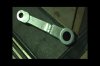
I had to do this for the same reasons you pointed out but, I still prefer this over moving the DLE to the underside. When you move the DLE to the bottom, it gives you the frame clearance you need but, it shortens the clearance between the DLE and the tie rod. This is not real obvious until you flex the drivers-side and stuff the tire up into the bump stops. Remember, the pitman arm is stationary but, the tie rod moves up & down with the axle. So make sure your bumps limit the up-travel before the pitman arm does (crunch!). You might want to consider making a custom flat pitman arm if you want to run the DLE on the bottom. This removes the dog-leg bend and moves the DLE up about an inch. Here's what my flat pitman looked like before I went back to the stock Nissan dog-leg arm...
View attachment 21690View attachment 21691
Damn with the tires lean like that...is almost like a motorcycle lol.
d103dbc9fa416b50f28150353de8be2a.jpg

How about bolting the pitman arm upside down so instead of hanging down it is hanging up toward the frame and install the tie rods under wouldn't that clear the frame. I'll check this and see what's up, if anything I'd do the same notch u did since I'm already working in the area.


Another question is there another way to make 3/4 inch hole aside from drill bits l, in trying to do them and so far I messed up one drill bit I can always replace them by going back and forth to Home Depot but that's tike consuming I don't have a torch or plasma cutter so I can not melt thru. I already use smaller bits to make the initial holes and increase in side to make them bigger but the 3/4 is really kicking my @$$

Sent from my SM-G930T using Tapatalk
 
Last edited:

4speedfunk

Well-Known Member
Messages
4,250
Location
Tardville
Unfortunately, the splined hole of the Nissan pitman arm is tapered...so it cannot be flipped. You can however cut the arm in half...flip the cut piece upside-down...and re-weld it. These pitman arms are forged (not cast) so it takes to welding without any issues. It is quite thick however, so you should make sure you do the welding with a serious welder with lots of amperage. I would recommend grinding 45-degree bevels into the areas you wish to weld. Then lay down a bead in the bottom of the v-trough, and then build it up with several layers of weld...making sure you get good penetration. Your steering (and life) depends on it. Its a common mod and there are lots of pics & tutorials on the internet...
pitman arm.jpg

I was not real excited about notching my frame but, when you look at how minimal the notch is, compared to the frame...its only about 15% of the frame's total height and I don't think it has any negative effects on strength. Just make sure you weld in a piece to replace the area you chop away.

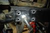
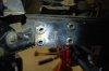
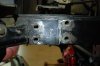
3/4" holes? I assume you are talking about holes for the steering box sleeves? I use a plasma cutter and blow the holes fairly close but, undersized. This leaves a jagged hole but, it only takes seconds. Then I shape the holes to final size using a high-speed pneumatic grinder (sounds like dentistry being performed).
DSC_0009.JPG
DSC_0010.JPG
DSC_0011.JPG

I've found that drilling large holes thru plate steel is much easier using reamers (instead of drills). A reamer works differently from a drill. It "scrapes" metal away from side of the hole, and this works much better than trying to shove a drill thru the metal from the top surface. Start with an 1/8" pilot hole, and then gradually increase the hole's diameter with increasing larger reamers (or a tapered reamer). You might try using a "step drill" or what some guys call a "uni-bit". These are essentially stepped "reamers", and they are fairly cheap but, make sure you use a big powerful drill because they put tremendous load on the motor...
https://www.amazon.com/CO-Z-Cobalt-...589293&sr=1-1-spons&keywords=step+drill&psc=1

Drilling the four holes on the outside is not a problem. But, trying to get a big, bulky drill in place on the inside will be very difficult due to the tight working space. Not to mention, the drill will physically wear you out after a couple holes (beer break). Sometimes using a drill turns into a wrestling match, especially with a large bit. On the other hand...the plasma torch (or Oxy/Act) takes only seconds. All you do is pull the trigger and melt the hole where you want it. No fuss, no cuss. A plasma cutter will pay for itself in a single SAS job. Then you can whore yourself out to all your friends, to help pay for it.

"He who owns the plasma, fears no metal".
 
Last edited:

Panzer07

Well-Known Member
Messages
2,548
Location
Ontario, CA
Unfortunately, the splined hole of the Nissan pitman arm is tapered...so it cannot be flipped. You can however cut the arm in half...flip the cut piece upside-down...and re-weld it. Then you can whore yourself out to all your friends, to help pay for it.

"He who owns the plasma, fears no metal".

I will go ahead and do that, as well ill watch some videos and even might weld some pieces of metal on all 4 sides for extra strength sort of like u do when u trying to secure a splinter I have a miller 251 so I think it can get hot enough so far has work flawlessly even for my rookie welding @$$.
I'll have to check the price of plasma cuter or if I can rent one...because using the drill does suck.

Sent from my SM-G930T using Tapatalk
 

Dana60H3

Active Member
Messages
43
Location
San Bernardino CA
When you get to the point in your build when you need a front driveshaft I have one that I originally used on mine. The double Cardan joint needs to be rebuilt on it though. But it is the correct flange that will bolt right up to your transfer case. Let me know if you are interested. I live close by in Devore.


Sent from my iPhone using Tapatalk
 

Panzer07

Well-Known Member
Messages
2,548
Location
Ontario, CA
When you get to the point in your build when you need a front driveshaft I have one that I originally used on mine. The double Cardan joint needs to be rebuilt on it though. But it is the correct flange that will bolt right up to your transfer case. Let me know if you are interested. I live close by in Devore.


Sent from my iPhone using Tapatalk
Appreciate the offer man , however I upgraded to the tatton driveshaft when I did the Rancho.

Sent from my SM-G930T using Tapatalk
 

06 H3

a.k.a. "The Jackal"
Messages
9,496
Location
Meridian, ID
When you get to the point in your build when you need a front driveshaft I have one that I originally used on mine. The double Cardan joint needs to be rebuilt on it though. But it is the correct flange that will bolt right up to your transfer case. Let me know if you are interested. I live close by in Devore.


Sent from my iPhone using Tapatalk

Is yours a high angle driveline?
 

Panzer07

Well-Known Member
Messages
2,548
Location
Ontario, CA
Are you going to Moab? I'd love to see this thing in person


Sent from my iPhone using Tapatalk
I'm aiming for it but yet I won't compromise since seems like every time I say something related to wheeling I jinx myself lol. I don't make it out for the first then the 2nd.

Sent from my SM-G930T using Tapatalk
 

Panzer07

Well-Known Member
Messages
2,548
Location
Ontario, CA
So now panzer is sitting at 29" (I must add I have a 1" body-lift so in reality it would be 28") from fender to hub matching the rear. I ended up with 32" lower control
a5912e639ee16e059da01a09ba6ae335.jpg


As u can see from the picture the drive shafts rod is about to slip off from the sleeve so I'm going to have to get a longer sleeve thingy about 3" longer since the exposed driveshaft rod is about 6"1/2, that way the drive shafts can collapse and expand nicely when flexing. I plan on unbolting the springs from the top and running a pice of tube welded to the coil bucket to allow more flex for the axle as well so it has a way to guide the spring in place, I'm trying to see if there are some sort of coil springs bearing that I can add to the top of coil bucket to make the compression of the spring more smoothly.

Turning radius I think it is good probably just as it was stock but not sure of that until I get driving I don't for see rub against the lower control arm on city driving or with full aired tires...however tire rub will be present when airdown.
5e795ca5315cfe19a5014304914b2a13.jpg

5a7aadcd2e0874fc9c9fcd72d983c770.jpg


There still quite a bunch of thing to get done before she is road and trail ready...slowly but shortly she is getting there.
I still need to weld the front bump-stop, either bolt or weld the airbags kit for the rear axle where the bump-stop used to be. Need to regear the front axle and drop a ox locker in it while at it, as well make front and rear lockers workable, I'm planning on using the air route instead of electronic, mainly because I'm already installing a on board air system for my airhorns and to make airing up tires faster.
Also need to install new bushings on the rear frame where leaf spring hangers bolt thru...not sure if I'm replacing leaf springs as well since the one I have are 10 years old and have 130k miles or so but since I'm running airbags in the rear I might just keep running them.
I also got to take it to the muffler shop and either delete the muffler and have the tube weld it to the Hmmvw's deep water fording exhaust pipe or delete the resonator and put the muffler in place of it I'm not sure of which route yet since I got hear it how it sounds in either configuration. But one thing if certain the muffler has to go from that location since there's where I plan to install my air tank/s not sure if I'm only running one or 2 my father in law work for a tank manufacturer company so I'm sure he could hook me up with a custom one if I ask him.
There are a bunch more little things but too many to list and not too relevant.


Sent from my SM-G930T using Tapatalk
 
Last edited:
4speedfunk

Well-Known Member
Messages
4,250
Location
Tardville
There are turning stops on your knuckles...(look on the inside edge at the rear of them). They are small bolts with a jamb nut on them. The factory sets these and then pops the jamb nut with a small bead of weld. Grab a grinder and knock the weld off them. This will allow you to spin the bolt & nut out. Run a tap thru the holes (5/16"-24 I think), and go get some new bolts & jamb nuts. Then you can adjust them to your liking, to prevent tire rub on the control arms...

hi-pin axle 008.JPG
 

Panzer07

Well-Known Member
Messages
2,548
Location
Ontario, CA
There are turning stops on your knuckles...(look on the inside edge at the rear of them). They are small bolts with a jamb nut on them. The factory sets these and then pops the jamb nut with a small bead of weld. Grab a grinder and knock the weld off them. This will allow you to spin the bolt & nut out. Run a tap thru the holes (5/16"-24 I think), and go get some new bolts & jamb nuts. Then you can adjust them to your liking, to prevent tire rub on the control arms...

View attachment 21750
Already on it CJ's, I got the knuckles from you so the new bolt and jam nut was there made it easier. Thank you

I sent u an email this morning but I'm not sure if u received it, I've been having troubles with either my email, or phone not sending emails.

Sent from my SM-G930T using Tapatalk
 

Panzer07

Well-Known Member
Messages
2,548
Location
Ontario, CA
Ok...couldn't remember if you got those from me or sourced your own.

Project looks good, by the way!
Thanks, I'm definitely satisfied with the outcome.

In case u don't receive my email I have a question regarding the passenger side wheel, it seems to me and my wife that it tilts/lean to the left is this an issue that can be fix by using the sleeves that u talk about in one of your youtube video I believe camber alignment. when I assemble the axle, joint and hubs I had almost 0° across the axle, I believe the pasanger side was the one that was a degree or 2 off.
40697fb1164eb9662cf60d36801d0ec1.jpg

fd93566f9233c6a85f3f0a38d68791f7.jpg

8308f825ad04e3b8020e21ea623dcf4c.jpg


Sent from my SM-G930T using Tapatalk
 

4speedfunk

Well-Known Member
Messages
4,250
Location
Tardville
GM axles typically have 1 to 1.5 degrees of positive camber built into them. This makes the top of the tires lean outward. Normally...this is okay and its not even noticeable with stock tires. But, when you put oversized tires on a stock axle, the problem gets amplified and you can usually see it with the naked eye. It can cause scuffing and tire wear on the outside edge of the tires, if not corrected. I prefer 0 camber, or close to it. If you can get it set to under half a degree, you'll be good.

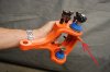
There are several methods for correcting camber on a solid axle. I prefer to use eccentric shims for camber adjustment. These are small threaded sleeves that get installed in the upper ball-joint holes. They thread in...just like the stock pre-load sleeves, except you orient them accordingly to re-position the upper ball joint further inboard. This tilts the tire inboard at the top, thus giving you the correction you need. These shims are available in .25 degree increments, from .25 up to 2.0 degrees. Beyond two degrees, you need to use an offset ball joint (probably not necessary). Obviously, measuring for the correct sleeve is critical. You must check, double-check, triple-check the difference between the axle tube angle and the hub angle. I use the same angle gauges you have, and its very difficult to measure such a small angle so take your time. For this reason, I keep a rather large assortment of these sleeves in house. That way I can play around with different sleeves until I find the sweet spot. I have tried several makes/models of these sleeves, and I feel the best ones are a one-piece design made by Specialty Products...
http://www.spcalignment.com/index.php?option=com_spc&task=part_description&pid=23012

You can get these at most auto parts stores but, they usually require you to order them. So like most items nowadays, I just get them online from Amazon or RockAuto. The part numbers I frequently use are listed below...

.50 degree #23004
.75 degree #23006
1.0 degree #23008
1.5 degree #23012

You will need a Dana 44/Corp 10b ball joint socket (spanner socket), to change the sleeves. Often times you must loosen both the lower and upper ball joints...wrap the top nut with a hammer...to relieve the preload pressure on the sleeve. If you try to back out the sleeve with the bottom ball joint fully torqued...it will usually strip the four notches out of the sleeve, or break the socket. You can change these after you get completely done but, its easier to do them with the axle on a workbench. Many times the original sleeves will be rusted in place...makes them a beyotch to remove. ALWAYS put some anti-seize on the new ones so the next guy (or you) won't have this problem.
 

Panzer07

Well-Known Member
Messages
2,548
Location
Ontario, CA
GM axles typically have 1 to 1.5 degrees of positive camber built into them. This makes the top of the tires lean outward. Normally...this is okay and its not even noticeable with stock tires. But, when you put oversized tires on a stock axle, the problem gets amplified and you can usually see it with the naked eye. It can cause scuffing and tire wear on the outside edge of the tires, if not corrected. I prefer 0 camber, or close to it. If you can get it set to under half a degree, you'll be good.

There are several methods for correcting camber on a solid axle. I prefer to use eccentric shims for camber adjustment. These are small threaded sleeves that get installed in the upper ball-joint holes. They thread in...just like the stock pre-load sleeves, except you orient them accordingly to re-position the upper ball joint further inboard. This tilts the tire inboard at the top, thus giving you the correction you need. These shims are available in .25 degree increments, from .25 up to 2.0 degrees. Beyond two degrees, you need to use an offset ball joint (probably not necessary). Obviously, measuring for the correct sleeve is critical. You must check, double-check, triple-check the difference between the axle tube angle and the hub angle. I use the same angle gauges you have, and its very difficult to measure such a small angle so take your time. For this reason, I keep a rather large assortment of these sleeves in house. That way I can play around with different sleeves until I find the sweet spot. I have tried several makes/models of these sleeves, and I feel the best ones are a one-piece design made by Specialty Products...
http://www.spcalignment.com/index.php?option=com_spc&task=part_description&pid=23012

You can get these at most auto parts stores but, they usually require you to order them. So like most items nowadays, I just get them online from Amazon or RockAuto. The part numbers I frequently use are listed below...

.50 degree #23004
.75 degree #23006
1.0 degree #23008
1.5 degree #23012

You will need a Dana 44/Corp 10b ball joint socket (spanner socket), to change the sleeves. Often times you must loosen both the lower and upper ball joints...wrap the top nut with a hammer...to relieve the preload pressure on the sleeve. If you try to back out the sleeve with the bottom ball joint fully torqued...it will usually strip the four notches out of the sleeve, or break the socket. You can change these after you get completely done but, its easier to do them with the axle on a workbench. Many times the original sleeves will be rusted in place...makes them a beyotch to remove. ALWAYS put some anti-seize on the new ones so the next guy (or you) won't have this problem.

Thanks cj for all the info...I'm gonna do this...i'll just order all sizes and just return the one I didn't need probably check at the local Napa first and go from there, I d9 have the spacer socket as well and it should be so hard to get them out since all is pretty much new. Anyways I'll use the "angle gauges" and the "eyeballing it sh!t" method and update accordingly.

Also I think this is a pretty good leaning right...not as cool as your custom one but decent.
5187a190491a45d0113a7408e79f26a8.jpg

60218f058b8dc513e8ef795e9e43d268.jpg

Perfect meme.
66dc81871df5c7ec40ebcdd1bce1b0e3.jpg


Sent from my SM-G930T using Tapatalk
 

Dana60H3

Active Member
Messages
43
Location
San Bernardino CA
How much if your selling it

The one I'm running now is a high angle. I just machined the stock flange to bolt up the flange of the double Cardan joint he uses for his extreme 42 degree CV shafts.
The old one is just a standard double cardan that I'm selling.


Sent from my iPhone using Tapatalk
 

GreatDaneHummer

Well-Known Member
Messages
994
Location
Chicago
Now that you have lived with your camo pattern for awhile how do you enjoy it? I have been going round and round with doing something like either of these.?


dNZ5saW.png

2587106490065125344KSnuZs_ph.jpg
 
Top